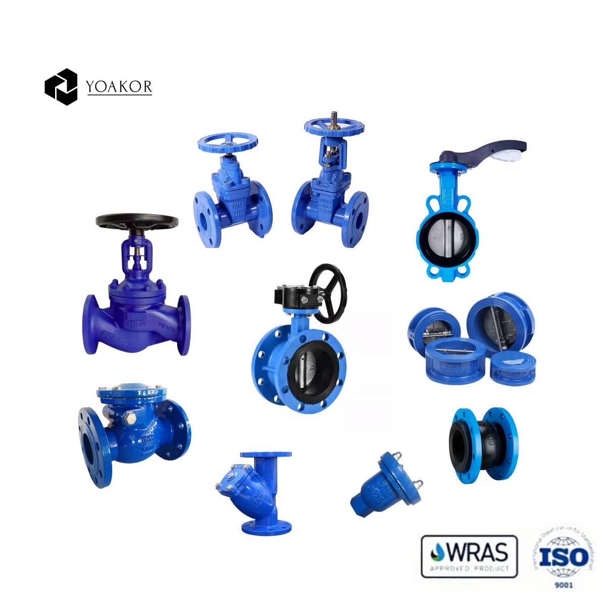


As a key control component in the fluid delivery system, the normal operation of the valve is crucial to the stability and safety of the entire system. The following are the detailed points for daily maintenance of the valve:
1. Appearance inspection
Cleaning the valve surface
Regularly clean the outer surface of the valve to remove impurities such as dust, oil, rust, etc. Use a clean, soft cloth or brush for cleaning. For stubborn stains, you can use an appropriate detergent, but be careful to avoid corrosion of the valve material by the detergent. For example, for stainless steel valves, you can use a mild alkaline detergent; for valves with painted surfaces, choose a detergent that will not damage the paint surface.
Clean the nameplate of the valve to ensure that the nameplate information is clear and readable. The nameplate contains important information such as the valve model, specification, pressure rating, and production date, which are very critical for operations such as valve maintenance, repair, and replacement.
Check the appearance integrity of the valve
Carefully check whether the valve body, bonnet, flange and other parts of the valve have cracks, deformation or signs of damage. Cracks may cause media leakage, and deformation may affect the normal operation and sealing performance of the valve. For cast iron valves, pay special attention to checking whether there are leaks caused by casting defects such as sand holes.
Check the connection parts of the valve, such as whether the bolts at the flange connection are loose, falling off or corroded. Loose bolts will affect the sealing performance of the flange and should be tightened in time; corroded bolts may need to be replaced to ensure the reliability of the connection. At the same time, check whether the gaskets at the connection parts are intact. If they are damaged or aged, they should be replaced in time.
Observe whether the operating parts of the valve, such as the handwheel, handle or electric actuator, are damaged, deformed or lost. These parts are the key to controlling the opening and closing of the valve. If damaged, the valve may not operate normally. For example, damage to the handwheel may prevent the operator from accurately controlling the opening of the valve.
2. Valve sealing inspection
External leakage inspection
For the valve stem sealing part of the valve, check whether there is medium leakage. You can apply a small amount of leak detection liquid (such as soapy water) around the valve stem to observe whether bubbles are generated. If there are bubbles, it means that there is leakage in the valve stem seal, and it is necessary to further check whether the sealing packing or seal is damaged or aged. The packing or seal may need to be replaced to solve the leakage problem.
Check whether there is leakage at the flange connection of the valve. You can also use leak detection liquid to observe whether there are bubbles coming out of the flange edge. For flanges with slight leakage, it may be necessary to retighten the bolts or replace the gaskets to repair the leakage. For serious leakage, it is necessary to close the upstream and downstream valves first, empty the medium in the pipeline, and then repair it.
Internal leakage inspection
Different methods are used to check internal leakage according to the type of valve and the working medium. For stop valves and gate valves, internal leakage can be judged by closing the valve and then observing whether there is medium flow downstream of the valve. For example, in a water system, it is possible to observe whether there is water seepage or pressure drop in the downstream pipeline; in a gas system, a gas detection instrument can be used to detect whether there is gas leakage downstream.
For ball valves and butterfly valves, internal leakage can be preliminarily judged by checking whether the position indicator is accurate after the valve is closed. If the position indicator shows that the valve is completely closed, but there is still medium leakage, there may be a problem with the seal between the ball or butterfly plate and the valve seat. It is necessary to further check whether the sealing surface of the valve seat is worn, scratched or attached with impurities, and grind or replace the valve seat if necessary.
3. Valve operation performance inspection
Manual valve operation inspection
Operate the manual valve regularly to check whether the valve is flexible in opening and closing. When opening and closing the valve, pay attention to whether the operating force is uniform, whether there is any stuck or abnormal resistance. If the operation is difficult, it may be caused by excessive friction between the valve stem and the packing, foreign matter stuck in the valve body, or damage to the valve parts.
Check whether the valve opening indication is accurate. For valves with opening indicators, such as regulating valves, observe whether the reading of the opening indicator matches the actual opening when operating the valve. Inaccurate opening indication may affect the flow control of the system, and the indicator needs to be calibrated or repaired.
For manual valves that are frequently operated, pay attention to the wear of the handwheel or handle. Excessively worn operating parts may affect the operator's feel and even cause uncontrolled operation. Severely worn handwheels or handles should be replaced in time to ensure the safety and accuracy of valve operation.
Electric valve operation inspection
Check whether the power connection of the electric valve is normal and whether the wires are damaged, aged or loose. Ensure that the control signal transmission of the electric actuator is normal. You can check whether the valve can accurately open, close or adjust the opening according to the instructions by operating the control system.
Observe the action of the electric valve during operation, such as whether the opening and closing speed of the valve meets the requirements, and whether there is abnormal vibration or noise. Abnormal vibration or noise may be caused by damage to the internal components of the electric actuator, failure of the valve mechanical structure or improper installation. Further inspection and maintenance of the electric valve is required, including checking the working status of components such as the motor, reducer, and coupling.
Regularly check and adjust the travel limit switch of the electric valve. The travel limit switch is an important device for controlling the opening and closing position of the valve. If the limit switch fails, it may cause the valve to open or close excessively, damaging the valve or the electric actuator. By simulating the full opening and closing actions of the valve, check whether the limit switch can accurately cut off the power supply of the motor to ensure the safe operation of the valve.
4. Lubrication and maintenance
Lubrication point inspection
Determine the lubrication points of the valve, generally including the valve stem, bearings, gears and other parts. For different types of valves, the location and number of lubrication points may be different. For example, the main lubrication points of the gate valve are the contact points between the valve stem and the gate and the guide rail; the ball valve needs to lubricate the contact points between the ball and the valve seat and the valve stem.
Check whether there is enough lubricant at the lubrication point. If the lubricant is insufficient, it may cause increased friction between components, affecting the operating performance and service life of the valve. For some valves with grease injection ports, you can judge whether the lubricant at the lubrication point is sufficient by observing the grease injection port or checking the grease level.
Choose the right lubricant
Choose the right lubricant according to the working environment of the valve and the material of the components. Under normal temperature and pressure conditions, lithium-based grease is a commonly used lubricant with good lubrication and wear resistance. For valves in high temperature environments, high-temperature resistant polyurea-based grease or perfluoropolyether grease can be selected; in low temperature environments, ester lubricants with good low-temperature fluidity are required.
For chemically corrosive working environments, such as valves in the chemical industry, lubricants with corrosion resistance should be selected. For example, fluoro grease can resist corrosion from strong acids, strong alkalis and other chemicals, providing effective lubrication and protection for valves. At the same time, the compatibility of lubricants with valve seals and other component materials should also be considered to avoid component damage due to the chemical properties of the lubricant.
Lubrication operation
For valves that need lubrication, lubricate them according to the correct method and cycle. For manual valves, you can use a grease gun or oil pot to inject lubricant into the lubrication point. When injecting lubricant, be careful to avoid excessive injection to prevent lubricant from overflowing and polluting the surrounding environment or affecting the normal operation of the valve. For electric valves, some electric actuators have their own lubrication system, which requires regular inspection and lubrication; for electric valves without their own lubrication system, the external lubrication points should be manually lubricated.
After lubrication, operate the valve several times so that the lubricant can be evenly distributed on the surface of the components to give full play to the lubrication effect. At the same time, clean up the lubricant that overflows during the lubrication process to keep the environment around the valve clean.
5. Valve accessories inspection
Filter inspection
If a filter is installed upstream of the valve, check the filter regularly for blockage. Blockage of the filter will cause a decrease in fluid flow and an increase in pressure loss, affecting the normal operation of the valve. The blockage can be determined by observing the pressure difference at both ends of the filter. When the pressure difference exceeds a certain limit, the filter needs to be cleaned or the filter element replaced.
When cleaning the filter, follow the correct operating procedures to avoid damaging the filter screen or other parts. For some precision filters, special cleaning equipment and cleaning agents may be required. After cleaning, make sure the filter is installed correctly and sealed well.
Pressure gauge and safety valve inspection
Check whether the pressure gauge near the valve is working properly. Observe whether the pointer of the pressure gauge can accurately indicate the pressure and whether the dial is clear and readable. If the pointer of the pressure gauge jumps, does not return to zero, or indicates inaccurately, it may be that the internal components of the pressure gauge are damaged or the pressure sensor is faulty, and the pressure gauge needs to be calibrated or replaced.
For systems with safety valves installed, check regularly whether the safety valve is in normal condition. Check whether the opening pressure of the safety valve meets the requirements and whether it can be accurately opened at the set pressure to release excess pressure. The performance of the safety valve can be checked by manual testing or professional testing equipment. At the same time, check the sealing performance of the safety valve to avoid leakage under normal working pressure.
The daily maintenance of valves requires meticulousness and patience. Through regular inspection and maintenance, possible problems with the valves can be discovered and solved in a timely manner, extending the service life of the valves and ensuring the safe and stable operation of the fluid delivery system.